¶ Hydrophone Board
This page will show how to connect to the board with a Windows operating system and what are the settings used for on the interface.
¶ How to connect to the board
Firstly, to connect to the board, you will need a USB-C to USB-A cable and a terminal application. For this example, I am using Tera Term. Connect the usb cable to the board and to your computer. After powering on the hydrophone board, a red light on it should turn on indicating that the board has been programmed with the on-board memory chip.
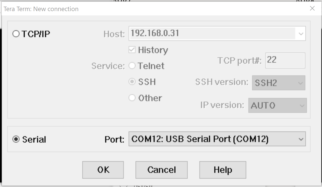
When opening the terminal application, you should see a COM port avaible for a connection. Here, COM12 is the hydrophone board.

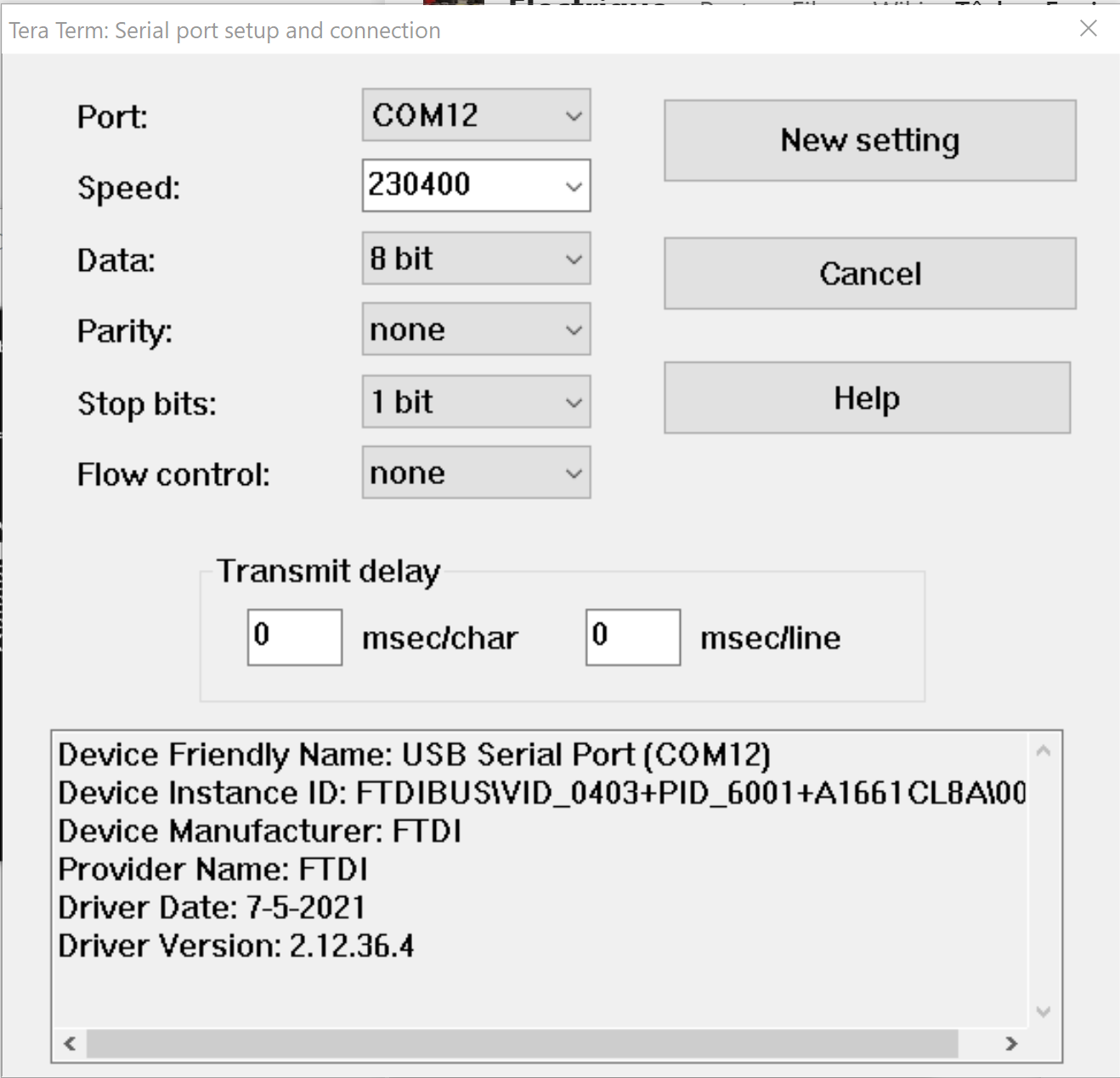
Now, the application is connected to the interface of the hydrophone. Still, nothing should happen since the default baud rate of the application is the right one. Select the baud rate 230400 and then press ENTER to see the interface appear.


You are now connected and ready to test and debug the hydrophone.
¶ How to use the interface
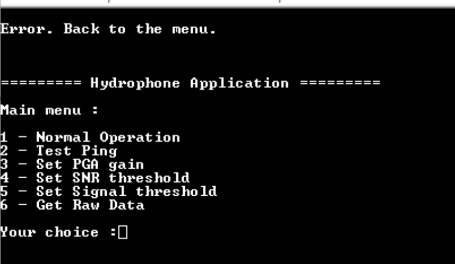
The application on the FPGA has 6 choices. The first, second and last are for obtaining different types of data and the others are to change the settings.
For the data, the normal operation return the values from the DOA algorithm implemented. The data is only output when a new sample is detected. The test ping is the same data but with only one output. Finally, the raw data is the voltage input on each ADC. The USB speed isn't fast enough to keep up with the 256 kHz clock of the ADC so the values are outputed in blocks out of a buffer. All of the returned strings have a XOR8 checksum at the end. Here is a example of the output of the raw data :

For the settings, here is a list of the different settings :
- Gain for the programmable gain amplifier
- Threshold of the signal to noise ratio
- Threshold for the reference signal
The gain affects the input signal of the hydrophones for the ADC. A lower gain is more appropriate for strong signal or with the pinger is close to the hydrophones and a higher gain is more appropriate for a lower signal or during normal use on the submarine.
The default value of the gain is 4. The range is between 0 and 7. The value 8 is to activate the automatic gain control (AGC, not implemented yet).
The threshold of the signal to noise ratio or SNR Threshold is used to reject the ping when the sum of of the value of the FFT divided by the maximum value found in the FFT is lower than the SNR Threshold.
The default value of the SNR Threshold is 10. There isn't any range except the value can't be negative.
Finally, the last setting is the signal threshold. This setting is used to enable the window function for the FFT of the signal received when the value is superior to the signal threshold.
The default value is 35000. This value works when the pinger isn't too far with the hydrophones. This value shouldn't go under 33000 since the average noise on the filtering board is between 32000 and 32500.
¶ How to debug the hydrophone
There isn't any specific ways to debug the hydrophone but when using the interface, there is some good practices :
- Put the SNR Threshold to 0 or 1. This will then accept all the pings from the hydrophones
- Reduce the Signal Threshold to around 32500. Under this value you will get in the constant noise of the filtering board and hydrophone.
- Increase the Gain of the programmable gain amplifier or turn off the AGC.
Be careful to not damaged the ADC by placing the pinger right in front of the hydrophones in the water with a gain of 7.