¶ Introduction
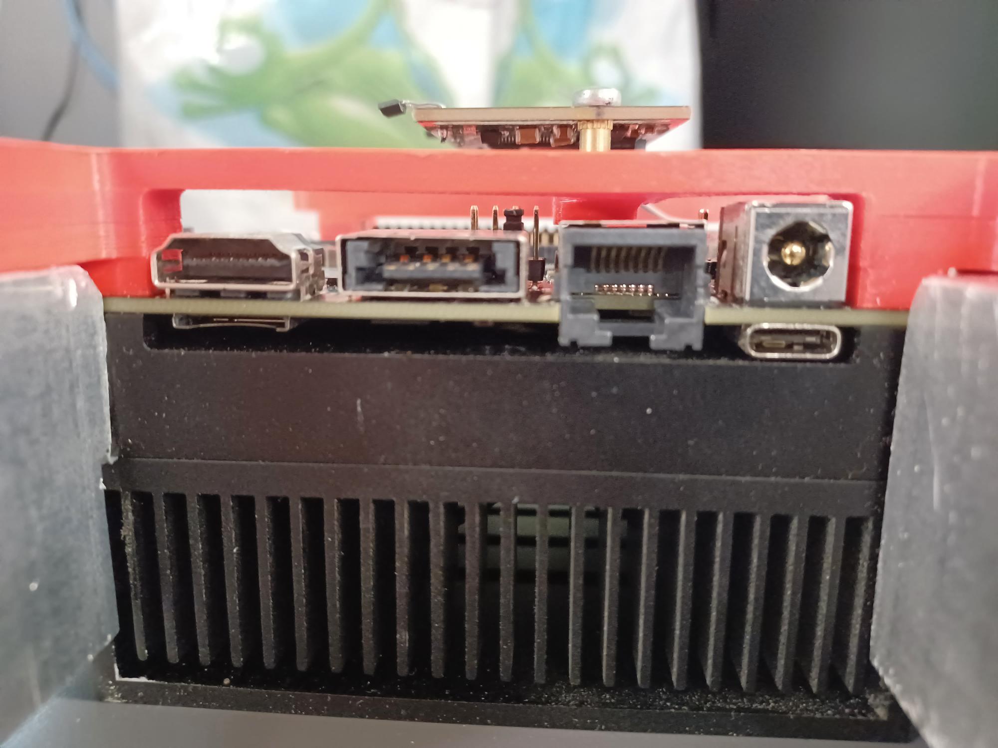
The Ethernet connector from carrier board from the Xavier developer kit does not rest directly on the PCB. Rather, it goes though the PCB, probably in a effort to reduce the height of the connector.

The side effect of this choice is that the Ethernet connector is very flimsy. Indeed, the Ethernet connector of one of our Xavier has been inadvertently removed from the PCB. As a temporary solution, we have re-solder the connector pin to the trace and have secure the connector with hot glue.
.png)
As a more permanent solution, we have decided to buy a Ethernet card that can be connected to the M.2 slot of the Xavier.
.jpg)
¶ Card Choice
We have decided to buy the Commell's M2-210. However, in the future we could also use the M.2 GbE from Connect Tech as it uses the same controller (Intel's I210AT).
%20card/M2-210/M2-210-3D-S.jpg)
¶ Connections
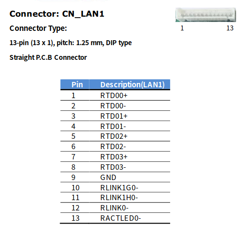
The Ethernet connector is on separate pcb from the rest of the card. The two PCBs are connected using a wire. On the main the PCB, the connector a single row and can only be inserted in one orientation. The pin out of the connector is presented below.

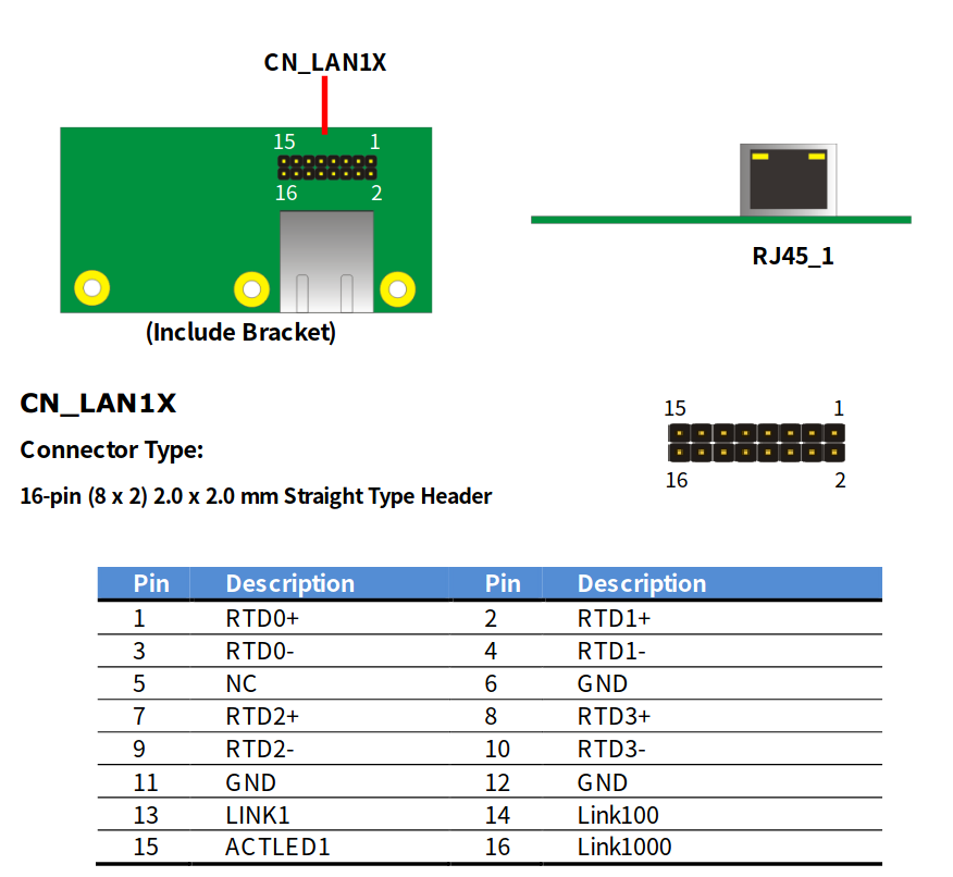
On the Ethernet PCB, the connector as two as two row and, despite the fact that the female connector is keyed, it can be inserted in both orientations. It is therefore very important to verify that the connector is in the correct orientation. As a rule of thumbs, the key of the female connector should be toward the ethernet connector. Below is the pinout of the connector.

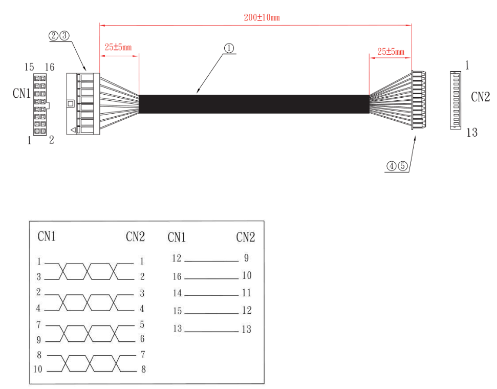
Below is the pin out of the connectors on the wire. (note that the pins 5, 6 and 11 of CN1 are not connected)

¶ Software setup
No drivers are required. You can verify that the card work correctly by entering "lspci" in a console. The card should appears as "Ethernet controller: Intel Corporation I210 Gigabit Network Connection (rev 03)" (see below).

Before using it in the sub, the interface needs to be configured to use a static IPv4 adress (192.168.0.31) see this page for more information.